When I first learned about engineering drawings, geometric tolerance symbols looked like a secret language.
These small marks carry a lot of information about how a part should be made, measured, and inspected.
If you work in manufacturing, machining, product design, or quality control, understanding these symbols can save time and prevent costly mistakes.
In this guide, you’ll learn what geometric tolerance symbols mean, how they are used, and how to read them with confidence.
Quick Answer: What Symbol Represents Geometric Tolerance Symbols?
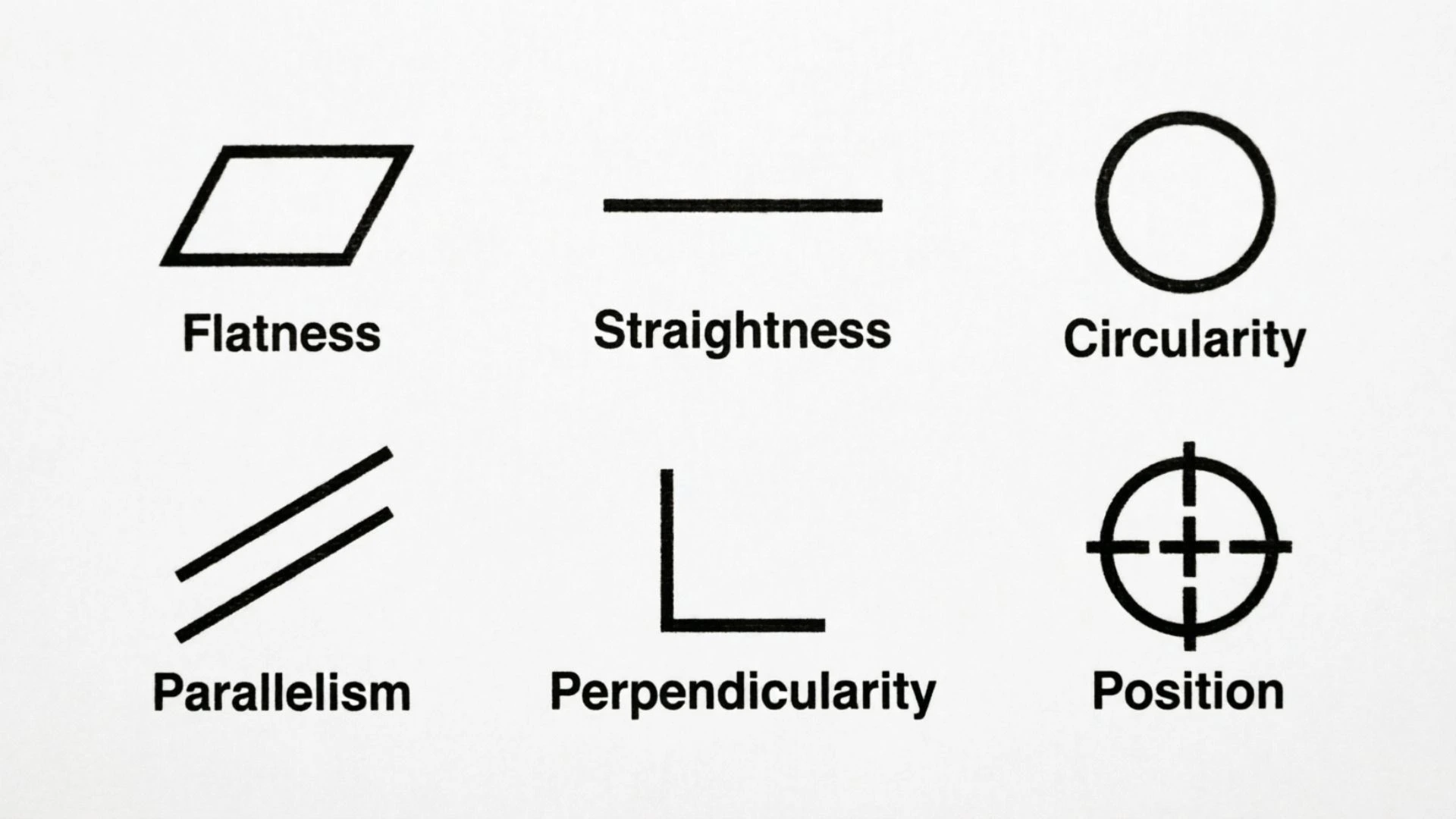
The most common way to represent geometric tolerance symbols is through GD&T (Geometric Dimensioning and Tolerancing) feature control symbols. These symbols define allowable variation in a part’s shape, size, location, orientation, and runout. Common examples include flatness, straightness, parallelism, perpendicularity, position, and concentricity symbols.
What Are Geometric Tolerance Symbols?
Geometric tolerance symbols are standardized symbols used in engineering drawings to communicate the exact requirements for a manufactured part. They are part of the GD&T system, which helps designers, machinists, and inspectors understand how much variation is acceptable during production.
Unlike simple measurements that only show size, geometric tolerances control the relationship between features. For example, a drawing may show the exact size of a hole, but a geometric tolerance symbol can specify where that hole must be located and how accurately it must align with other features.
These symbols represent different types of controls:
- Form controls – define the shape of individual features.
- Orientation controls – describe how features should angle or align.
- Location controls – control the exact placement of features.
- Runout controls – manage rotation-related accuracy.
The meaning of a symbol depends on its engineering context. In technical drawings, standards, and manufacturing documents, these symbols have precise definitions. They should not be confused with decorative symbols or general design icons.
Geometric Tolerance Symbols Comparison Table
| Symbol | Main Meaning | Best Use |
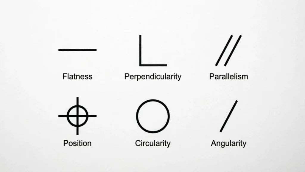
| Straightness | Controls how straight a feature must be | Shafts, edges, surfaces |
| Flatness | Controls surface evenness | Machined faces, sealing surfaces |
| Circularity | Controls roundness | Cylinders, holes, pins |
| Cylindricity | Controls overall cylindrical shape | Precision shafts and bores |
| Parallelism | Controls parallel alignment | Mating surfaces |
| Perpendicularity | Controls 90-degree alignment | Frames, holes, machine parts |
| Angularity | Controls feature angle | Sloped surfaces |
| Position | Controls exact feature location | Hole patterns and assemblies |
| Concentricity | Controls shared center alignment | Rotating components |
| Symmetry | Controls balanced feature placement | Centered designs |
| Circular Runout | Controls surface variation during rotation | Bearings, shafts |
| Total Runout | Controls complete rotating surface accuracy | High-precision parts |
Top 12 Geometric Tolerance Symbols and Their Meanings
Straightness: Controlling Linear Accuracy
The straightness symbol controls how much a line element or axis can vary from a perfectly straight condition. It is commonly used when a part needs accurate alignment along its length.
For example, a shaft may need a specific straightness tolerance so it can rotate smoothly inside an assembly. Without this control, even a small bend could cause vibration, wear, or failure.
Straightness is one of the simpler geometric controls because it focuses on one feature rather than comparing multiple surfaces.
Today, engineers use straightness requirements in automotive parts, aerospace components, tools, and precision machinery.
Best for: shafts, rods, edges, machine components, precision manufacturing
Flatness: Creating Even and Reliable Surfaces
Flatness defines how much a surface can differ from a perfectly flat plane. It does not depend on another feature, making it a form tolerance.
A flat surface is important when two components must fit together evenly. For example, engine parts, electronic housings, and sealing surfaces often require controlled flatness.
In manufacturing, flatness helps prevent gaps, leaks, and uneven contact between parts.
Unlike some GD&T symbols, flatness does not require a reference point or datum. It simply ensures that the surface stays within the allowed tolerance zone.
Best for: machine surfaces, gaskets, assembly parts, precision plates
Circularity: Maintaining Round Shape
Circularity, also called roundness, controls how close a circular feature must be to a perfect circle. It applies to individual circular surfaces without using a datum reference.
This symbol is important for parts that rotate or fit together with other round components. A hole, bearing seat, or cylinder may look correct by measurement but still fail if its shape is slightly uneven.
Manufacturers use circularity requirements to improve reliability and reduce friction.
Best for: holes, cylinders, bearings, rotating components, mechanical fittings
Cylindricity: Controlling Complete Cylinder Form
Cylindricity controls the entire surface of a cylindrical feature. It combines aspects of circularity and straightness to ensure the cylinder maintains accurate shape along its full length.
This tolerance is useful for high-precision parts where movement and fit are critical. A hydraulic cylinder, for example, requires excellent cylindrical accuracy to prevent leaks and performance problems.
Because cylindricity controls the whole surface, it is often used in demanding engineering applications.
Best for: hydraulic parts, precision shafts, tubes, industrial equipment
Parallelism: Keeping Features Properly Aligned
Parallelism controls whether one surface or feature stays parallel to a reference feature. It helps ensure parts align correctly during assembly.
For example, two machine surfaces may need to remain parallel so they distribute force evenly. Incorrect alignment can create stress, uneven wear, or assembly problems.
Parallelism is widely used in manufacturing because many mechanical systems depend on accurate alignment.
Best for: machine beds, sliding parts, assembled components, guides
Perpendicularity: Maintaining Right-Angle Accuracy
Perpendicularity controls whether a feature is exactly 90 degrees from a reference surface or axis.
This symbol is especially important in parts that must fit together at right angles. A small error can create problems when assembling multiple components.
Common examples include drilled holes, mounting surfaces, and structural components.
Best for: brackets, holes, frames, mounting parts, assemblies
Angularity: Controlling Specific Angles
Angularity controls a feature at a specified angle other than basic horizontal or vertical alignment.
Engineers use angularity when a surface, hole, or feature must maintain a precise slope. It provides more control than simply writing an angle measurement.
This tolerance appears in many industries where angled surfaces affect performance and assembly.
Best for: angled surfaces, cutting tools, aerospace parts, mechanical designs
Position: The Most Common Location Control
The position symbol controls the exact location of a feature, especially holes and slots. It is one of the most frequently used GD&T symbols.
A position tolerance ensures that features are placed correctly relative to reference points called datums. This improves interchangeability because parts can be assembled consistently.
Modern manufacturing relies heavily on position tolerances for complex components.
Best for: bolt holes, assemblies, CNC machining, production parts
Concentricity: Aligning Shared Centers
Concentricity controls whether two cylindrical features share the same center axis. It is used when precise rotational alignment is necessary.
Although it has a specific meaning in GD&T, many modern applications use other methods, such as position tolerance, because they can be easier to inspect.
Concentricity remains important in specialized precision applications.
Best for: rotating parts, shafts, precision instruments, mechanical systems
Circular Runout: Improving Rotating Accuracy
Circular runout controls how much a surface can vary when a part rotates around a reference axis.
It is commonly used for rotating components because even small variations can create vibration or uneven operation.
Manufacturers use circular runout requirements in parts that need smooth and reliable motion.
Best for: wheels, shafts, bearings, rotating machinery
Total Runout: Full Surface Rotation Control
Total runout controls the entire surface variation of a rotating feature. It is a more comprehensive control than circular runout.
It is often applied to high-performance components where accuracy across the complete surface matters.
Industries such as aerospace, automotive, and precision manufacturing use total runout to maintain quality.
Best for: precision shafts, turbines, rotating equipment, advanced machinery
Best Geometric Tolerance Symbols for Tattoos
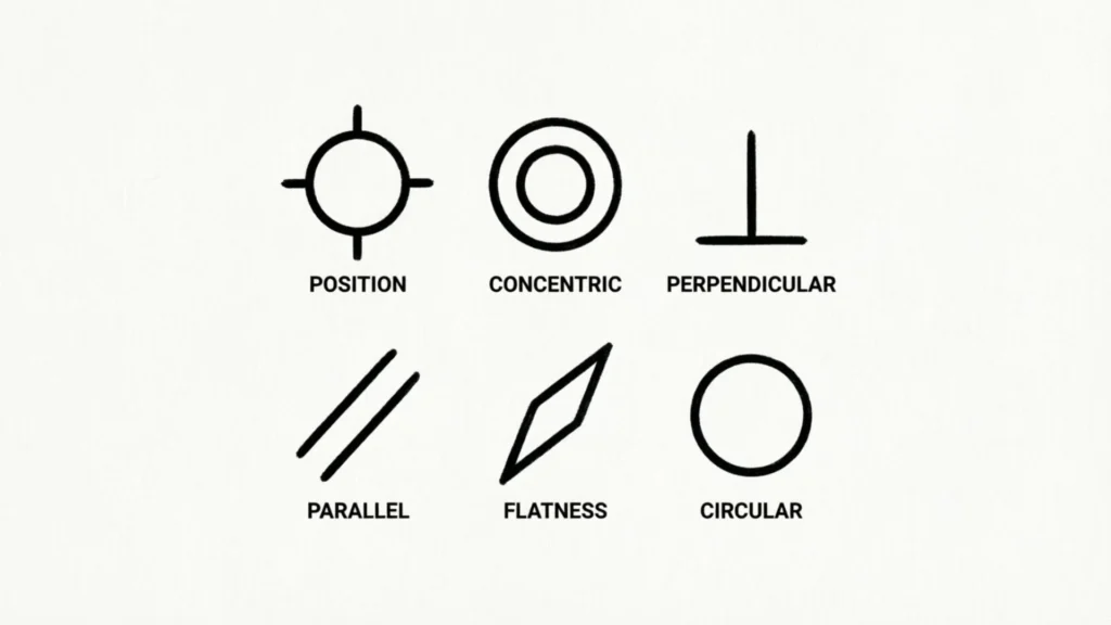
Although geometric tolerance symbols are mainly technical marks, some people choose engineering symbols as tattoos because they represent interests such as design, craftsmanship, problem-solving, or a passion for manufacturing.
The best tattoo choices are usually simple symbols with personal meaning. A small GD&T symbol can represent attention to detail, engineering identity, or a love of creating things.
Popular ideas include:
- Position symbol for precision and accuracy
- Flatness symbol for balance and consistency
- Straightness symbol for discipline and direction
- A custom engineering drawing design combining multiple symbols
- A blueprint-style tattoo featuring GD&T elements
Before getting a technical symbol tattoo, it is worth confirming its exact meaning. A small mistake in a tattoo can completely change the message.
Best Geometric Tolerance Symbols for Logos and Design
Geometric tolerance symbols can work well in logos and creative designs when they are used carefully. Their clean lines and technical appearance make them attractive for engineering companies, manufacturing brands, educational projects, and design communities.
A good logo symbol should be:
- Easy to recognize
- Simple at small sizes
- Connected to the brand identity
- Accurate in meaning
Engineering businesses may use GD&T-inspired graphics to communicate precision, quality, and technical expertise. However, companies should avoid using symbols incorrectly because technical audiences may notice errors.
Best Geometric Tolerance Symbols for Family, Spiritual, or Personal Meaning
Geometric tolerance symbols are not traditionally spiritual or cultural symbols. Their meaning comes mainly from engineering standards and personal interpretation.
For personal use, people often connect these symbols with ideas such as:
- Precision in life decisions
- Balance and organization
- Building or creating something meaningful
- Appreciation for engineering skills
- Family members who work in technical fields
A blueprint-style family artwork, for example, may combine names, dates, and engineering symbols to honor a loved one’s profession or passion.
Before Using Cultural or Sacred Symbols
Geometric tolerance symbols do not have traditional religious meanings, but many symbols in design and art do have cultural or spiritual backgrounds.
When using any symbol in tattoos, logos, products, or artwork, it is important to understand its origin. Some symbols may have deep meaning within certain communities, and using them without knowledge can create misunderstandings.
Always research the background of a symbol and respect the traditions connected to it.
How to Choose the Right Symbol for Geometric Tolerance Symbols
Choosing the right geometric tolerance symbol depends on your purpose.
Consider these questions:
- Are you learning GD&T for engineering work?
- Are you designing a tattoo or personal artwork?
- Do you need a symbol for a company logo?
- Does the symbol accurately match your intended message?
- Is the design simple enough to understand?
For engineering use, accuracy matters most. For creative use, clarity and personal connection are important. A symbol should communicate the idea you want people to understand.
FAQs About Geometric Tolerance Symbols
What is the best symbol for geometric tolerance symbols?
The best symbol depends on the application. The position symbol is one of the most commonly used GD&T symbols because it controls the location of important features like holes. However, flatness, straightness, and runout symbols may be more suitable for specific manufacturing needs.
What symbol represents precision in engineering?
The position tolerance symbol is often associated with precision because it controls the exact location of features. Other symbols, such as flatness and straightness, also represent careful control of manufacturing accuracy.
What is a good geometric tolerance symbol tattoo?
A good GD&T tattoo is usually a simple symbol with personal meaning. Engineers may choose a position, flatness, or straightness symbol because these marks connect with ideas like accuracy, design, and craftsmanship.
What symbol represents accuracy?
Several geometric tolerance symbols represent accuracy in different ways. Position represents accurate placement, flatness represents surface accuracy, and straightness represents linear accuracy.
What is the simplest geometric tolerance symbol?
Straightness and flatness are among the simplest GD&T symbols to understand because they control individual features without complex relationships between multiple parts.
Are geometric tolerance symbols used in logos?
Yes, some engineering companies and design brands use GD&T-inspired visuals in logos. They should be used carefully and correctly so the symbol communicates the intended technical message.
Do geometric tolerance symbols have spiritual meanings?
No, geometric tolerance symbols are technical engineering symbols rather than spiritual symbols. Personal interpretations may vary, but their official meanings come from engineering standards.
Final Thoughts
Understanding geometric tolerance symbols helps bridge the gap between design ideas and real-world manufacturing. These small marks provide important instructions that improve accuracy, quality, and communication between engineers and manufacturers.
Whether you are studying GD&T, creating technical artwork, or exploring engineering-inspired designs, knowing the meaning behind each symbol helps you use them with confidence. The right symbol is not just a mark on a drawing it is a clear message about how something should be made.

Lily Anderson is a passionate writer who enjoys turning everyday ideas into engaging and easy-to-read stories. She loves creating content that helps readers learn something new while keeping them entertained. Lily is the author of the original titles Whispers Between Ordinary Days and The Quiet Map of Tomorrow. When she’s not writing, she enjoys reading, exploring new places, and finding inspiration in everyday life. Her goal is to create meaningful content that readers can connect with and remember.
 Adam Sullivan
 Dylan Anderson