Truth tables make Boolean logic easier to understand by showing every possible input combination and the output produced by a logical operation. If you are learning computer science, discrete mathematics, digital electronics, or programming, understanding truth table symbols is an important first step.
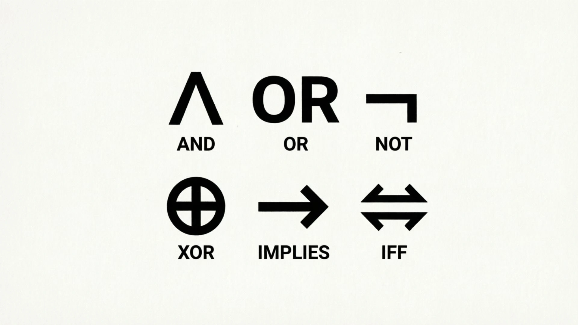
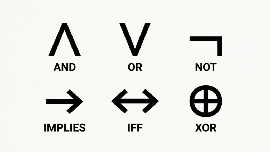
The symbols may look confusing at first. You might see ∧, ∨, ¬, ⊕, →, or ↔ and wonder what each one means. You may also encounter AND, OR, NOT, NAND, NOR, XOR, and XNOR gates in electronics diagrams.
The good news is that the basic ideas are simple once you connect each symbol with its meaning and truth table.
This guide explains the most common truth table symbols, their names, Boolean notation, logic-gate relationships, and practical examples. It also explains how many rows a truth table needs, how to create one, how to read compound expressions, and how mathematical notation differs from programming notation.
What Are Truth Table Symbols? (Quick Answer)
Truth table symbols are mathematical, logical, or Boolean notations used to represent logical operations and values.
The most common symbols include:
| Symbol | Name | Basic Meaning | Example |
| 0 | False | Logical false | A = 0 |
| 1 | True | Logical true | A = 1 |
| ∧ | AND | Both conditions must be true | A ∧ B |
| ∨ | OR | At least one condition is true | A ∨ B |
| ¬ | NOT | Reverses a logical value | ¬A |
| ⊕ | XOR | Exactly one input is true | A ⊕ B |
| → | Implication | If A, then B | A → B |
| ↔ | Biconditional | A and B have the same truth value | A ↔ B |
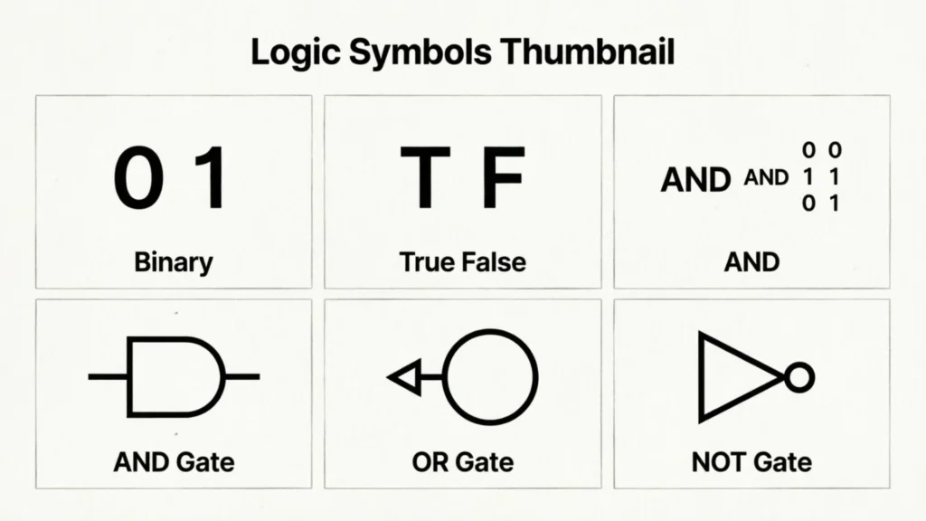
In digital electronics, these logical operations are also represented by graphical logic-gate symbols such as AND, OR, NOT, NAND, NOR, XOR, and XNOR.
Truth Table Symbols and Meanings
Before working with complete truth tables, it helps to understand the basic notation.
Boolean Values: 0 and 1
Truth tables commonly use two values:
- 0 = False
- 1 = True
For example:
| A | Meaning |
| 0 | A is false |
| 1 | A is true |
In digital electronics, 0 and 1 can also represent different electrical signal states. The exact voltage interpretation depends on the technology and circuit design, so 0 and 1 should first be understood as logical states.
Boolean Variables
Letters such as A, B, C, X, Y, and Q are often used as Boolean variables.
A variable can have one of two basic values:
A = 0
or
A = 1
With two variables, such as A and B, there are four possible input combinations:
| A | B |
| 0 | 0 |
| 0 | 1 |
| 1 | 0 |
| 1 | 1 |
Adding another independent variable doubles the number of possible combinations.
AND Symbol: ∧
The symbol ∧ represents logical AND.
The expression:
A ∧ B
is true only when both A and B are true.
| A | B | A ∧ B |
| 0 | 0 | 0 |
| 0 | 1 | 0 |
| 1 | 0 | 0 |
| 1 | 1 | 1 |
A simple way to remember AND is:
AND means both.
OR Symbol: ∨
The symbol ∨ represents logical OR.
The expression:
A ∨ B
is true when at least one input is true.
| A | B | A ∨ B |
| 0 | 0 | 0 |
| 0 | 1 | 1 |
| 1 | 0 | 1 |
| 1 | 1 | 1 |
Remember:
OR means one or both.
This is different from XOR, which requires exactly one true input.
NOT Symbol: ¬
The symbol ¬ means NOT.
It reverses the truth value of an input.
| A | ¬A |
| 0 | 1 |
| 1 | 0 |
So:
- NOT 0 = 1
- NOT 1 = 0
Other notations for NOT may include an overbar, apostrophe, or programming operator such as !, depending on the context.
XOR Symbol: ⊕
The symbol ⊕ commonly represents exclusive OR, or XOR.
XOR produces 1 when the inputs are different.
| A | B | A ⊕ B |
| 0 | 0 | 0 |
| 0 | 1 | 1 |
| 1 | 0 | 1 |
| 1 | 1 | 0 |
The easiest memory rule is:
XOR means exactly one.
Implication Symbol: →
The symbol → is commonly used for logical implication.
The expression:
A → B
can be read as:
If A, then B.
The implication is false only when A is true and B is false.
| A | B | A → B |
| 0 | 0 | 1 |
| 0 | 1 | 1 |
| 1 | 0 | 0 |
| 1 | 1 | 1 |
Implication is common in mathematical and propositional logic and is different from a physical logic-gate symbol.
Biconditional Symbol: ↔
The symbol ↔ represents a biconditional relationship.
The expression:
A ↔ B
is true when A and B have the same truth value.
| A | B | A ↔ B |
| 0 | 0 | 1 |
| 0 | 1 | 0 |
| 1 | 0 | 0 |
| 1 | 1 | 1 |
A useful memory rule is:
Biconditional means both match.
Truth Table Symbols Chart
The following chart provides a quick reference for commonly encountered notation.
| Symbol | Name | Meaning | True When |
| 0 | False | False logical value | The statement is false |
| 1 | True | True logical value | The statement is true |
| ∧ | AND | Logical conjunction | Both inputs are true |
| ∨ | OR | Logical disjunction | At least one input is true |
| ¬ | NOT | Logical negation | The input is false |
| ⊕ | XOR | Exclusive OR | Inputs are different |
| → | Implication | Conditional relationship | A is false or B is true |
| ↔ | Biconditional | Two-way equivalence | Inputs have the same value |
| ⊤ | Tautology | Always true | Every allowed case |
| ⊥ | Contradiction | Always false | No allowed case |
Notation can vary between textbooks, mathematical disciplines, programming languages, and engineering contexts. Always check the notation defined by the course, textbook, circuit diagram, or documentation you are using.
Basic Logic Gate Symbols and Truth Tables
Truth tables and logic gates are closely connected.
A truth table describes what a logical operation does. A logic-gate diagram represents that operation graphically in a digital circuit.
AND Gate Symbol and Truth Table
An AND gate produces a true output only when all of its inputs are true.
For two inputs:
| A | B | Output |
| 0 | 0 | 0 |
| 0 | 1 | 0 |
| 1 | 0 | 0 |
| 1 | 1 | 1 |
Boolean expression:
Q = A ∧ B
In Boolean algebra, AND may also be written using a dot:
Q = A · B
In some contexts, multiplication-like notation or simple adjacency can also represent AND.
OR Gate Symbol and Truth Table
An OR gate produces 1 when one or more inputs are 1.
| A | B | Output |
| 0 | 0 | 0 |
| 0 | 1 | 1 |
| 1 | 0 | 1 |
| 1 | 1 | 1 |
Boolean expression:
Q = A ∨ B
In Boolean algebra, OR is often represented by a plus sign:
Q = A + B
The plus sign here represents Boolean OR, not ordinary arithmetic addition.
NOT Gate Symbol and Truth Table
A NOT gate has one input and produces the opposite logical value.
| A | Output |
| 0 | 1 |
| 1 | 0 |
Expression:
Q = ¬A
It may also be written as:
Q = A̅
or:
Q = A’
depending on the notation system.
NAND Gate Symbol and Truth Table
NAND means:
NOT AND
It first performs AND and then reverses the result.
| A | B | AND | NAND |
| 0 | 0 | 0 | 1 |
| 0 | 1 | 0 | 1 |
| 1 | 0 | 0 | 1 |
| 1 | 1 | 1 | 0 |
NAND is therefore false only when every input is true.
NOR Gate Symbol and Truth Table
NOR means:
NOT OR
It performs OR and then reverses the result.
| A | B | OR | NOR |
| 0 | 0 | 0 | 1 |
| 0 | 1 | 1 | 0 |
| 1 | 0 | 1 | 0 |
| 1 | 1 | 1 | 0 |
NOR is true only when all inputs are false.
XOR Gate Symbol and Truth Table
XOR means exclusive OR.
It produces 1 when the inputs are different.
| A | B | XOR |
| 0 | 0 | 0 |
| 0 | 1 | 1 |
| 1 | 0 | 1 |
| 1 | 1 | 0 |
XOR is especially important when a circuit needs to detect whether two signals differ.
XNOR Gate Symbol and Truth Table
XNOR is the opposite of XOR.
It produces 1 when both inputs have the same value.
| A | B | XOR | XNOR |
| 0 | 0 | 0 | 1 |
| 0 | 1 | 1 | 0 |
| 1 | 0 | 1 | 0 |
| 1 | 1 | 0 | 1 |
A simple memory trick is:
XOR = different. XNOR = same.
Complete Logic Gate Truth Table
For quick comparison, here are the standard two-input results for the most common basic gates.
| A | B | AND | OR | NAND | NOR | XOR | XNOR |
| 0 | 0 | 0 | 0 | 1 | 1 | 0 | 1 |
| 0 | 1 | 0 | 1 | 1 | 0 | 1 | 0 |
| 1 | 0 | 0 | 1 | 1 | 0 | 1 | 0 |
| 1 | 1 | 1 | 1 | 0 | 0 | 0 | 1 |
For NOT, there is only one input:
| A | NOT A |
| 0 | 1 |
| 1 | 0 |
This master table is useful as a quick reference when studying Boolean logic or digital circuits.
Truth Table Symbols vs Logic Gate Symbols
Truth-table notation and logic-gate symbols are related, but they are not identical.
| Feature | Truth Table | Logic Gate |
| Main purpose | Shows input/output behavior | Represents a circuit operation |
| Format | Rows and columns | Graphical symbol |
| Example | A ∧ B | AND gate drawing |
| Used in | Logic, mathematics, computing | Digital electronics |
| Shows every combination? | Yes, for a complete table | No |
A truth table tells you what happens.
A logic-gate diagram shows how the operation is represented in a circuit.
For example, an AND gate can be represented by a graphical gate symbol, while its behavior can be described by:
Q = A ∧ B
and demonstrated using an AND truth table.
Boolean Logic Symbols in Different Notations
The same logical concept can appear in different forms depending on the field.
Mathematical Notation
Mathematical logic commonly uses symbols such as:
- ∧ for AND
- ∨ for OR
- ¬ for NOT
- → for implication
- ↔ for biconditional
- ⊕ for XOR
These are especially common in discrete mathematics, logic courses, and theoretical computer science.
Boolean Algebra Notation
Boolean algebra often uses:
- + for OR
- · for AND
- overbar or apostrophe for NOT
For example:
A + B
means Boolean OR.
A · B
means Boolean AND.
A̅
means NOT A.
This notation should not be confused with ordinary arithmetic.
Programming Notation
Programming languages often use symbols that differ from mathematical logic.
For example, languages in the C-style family commonly use:
- && for logical AND
- || for logical OR
- ! for logical NOT
Equality and inequality operators can also appear in Boolean expressions:
- == means equality comparison in many languages
- != means not equal in many languages
Programming syntax varies by language, so you should always check the syntax for the specific language you are using.
How to Read a Truth Table
Reading a truth table becomes easy when you follow a consistent process.
Step 1: Identify the Inputs
Look at the input columns.
For example:
A and B
are two Boolean inputs.
Step 2: Count the Possible Combinations
Two inputs produce four combinations:
- 00
- 01
- 10
- 11
Step 3: Find the Operation
Look at the expression.
For example:
A ∧ B
means AND.
Step 4: Apply the Rule
AND requires both inputs to be 1.
Therefore:
- 0 AND 0 = 0
- 0 AND 1 = 0
- 1 AND 0 = 0
- 1 AND 1 = 1
Step 5: Read the Output
The final column gives the result for each input combination.
How Many Rows Does a Truth Table Have?
The number of rows in a complete truth table depends on the number of independent Boolean inputs.
The formula is:
2ⁿ
where n is the number of inputs.
| Number of Inputs | Number of Combinations |
| 1 | 2 |
| 2 | 4 |
| 3 | 8 |
| 4 | 16 |
| 5 | 32 |
| 6 | 64 |
| 7 | 128 |
| 8 | 256 |
For example, with three variables—A, B, and C—you need:
2³ = 8
possible input combinations.
This formula helps you determine how many rows a complete truth table requires.
How to Create a Truth Table
Creating a truth table is easier if you work from the inputs toward the final output.
One-Input Example
Consider:
F = ¬A
The table is:
| A | F |
| 0 | 1 |
| 1 | 0 |
The output simply reverses the input.
Two-Input Example
Consider:
F = A ∧ B
Start with every combination:
| A | B |
| 0 | 0 |
| 0 | 1 |
| 1 | 0 |
| 1 | 1 |
Then apply AND:
| A | B | F |
| 0 | 0 | 0 |
| 0 | 1 | 0 |
| 1 | 0 | 0 |
| 1 | 1 | 1 |
Three-Input Example
For A, B, and C, there are eight combinations:
| A | B | C |
| 0 | 0 | 0 |
| 0 | 0 | 1 |
| 0 | 1 | 0 |
| 0 | 1 | 1 |
| 1 | 0 | 0 |
| 1 | 0 | 1 |
| 1 | 1 | 0 |
| 1 | 1 | 1 |
You can then add columns for intermediate operations and the final result.
Compound Boolean Expressions and Truth Tables
A compound expression contains more than one logical operation.
For example:
F = (A ∧ B) ∨ C
The best approach is to calculate the smaller operation first.
Worked Example
First calculate:
A ∧ B
Then combine that result with C using OR.
| A | B | C | A ∧ B | F = (A ∧ B) ∨ C |
| 0 | 0 | 0 | 0 | 0 |
| 0 | 0 | 1 | 0 | 1 |
| 0 | 1 | 0 | 0 | 0 |
| 0 | 1 | 1 | 0 | 1 |
| 1 | 0 | 0 | 0 | 0 |
| 1 | 0 | 1 | 0 | 1 |
| 1 | 1 | 0 | 1 | 1 |
| 1 | 1 | 1 | 1 | 1 |
Intermediate columns are useful because they break a complicated expression into smaller steps.
Why Parentheses Matter
Compare:
¬(A ∧ B)
with:
(¬A) ∧ B
They are different expressions and generally produce different results.
Parentheses show which operation should be evaluated together.
OR vs XOR: What’s the Difference?
OR and XOR are two of the most commonly confused logical operations.
OR
OR is true when at least one input is true.
XOR
XOR is true only when exactly one input is true.
Compare them:
| A | B | OR | XOR |
| 0 | 0 | 0 | 0 |
| 0 | 1 | 1 | 1 |
| 1 | 0 | 1 | 1 |
| 1 | 1 | 1 | 0 |
The important difference appears in the final row.
OR: 1 OR 1 = 1
XOR: 1 XOR 1 = 0
A simple memory trick:
OR allows both. XOR excludes both.
What Does the Bubble Mean on a Logic Gate?
A small circle, often called an inversion bubble, on a logic-gate diagram indicates that the signal at that point is inverted.
For example, an AND gate with an inverted output behaves as a NAND gate.
An OR gate with an inverted output behaves as a NOR gate.
An XOR gate with an inverted output behaves as an XNOR gate.
The bubble can also appear on an input, indicating that the input signal is inverted before being used by the gate.
This graphical notation is especially important when reading digital circuit diagrams.
Implication and Biconditional Symbols
Not every truth-table symbol represents a physical logic gate.
Symbols such as → and ↔ are common in propositional logic and mathematics.
Implication Truth Table
For:
A → B
the statement is false only when A is true and B is false.
| A | B | A → B |
| 0 | 0 | 1 |
| 0 | 1 | 1 |
| 1 | 0 | 0 |
| 1 | 1 | 1 |
Biconditional Truth Table
For:
A ↔ B
the result is true when both values match.
| A | B | A ↔ B |
| 0 | 0 | 1 |
| 0 | 1 | 0 |
| 1 | 0 | 0 |
| 1 | 1 | 1 |
These symbols are especially useful when studying propositions, proofs, and discrete mathematics.
De Morgan’s Laws and Truth Tables
De Morgan’s laws describe important relationships between NOT, AND, and OR.
The two standard forms are:
¬(A ∧ B) = ¬A ∨ ¬B
and:
¬(A ∨ B) = ¬A ∧ ¬B
In simple language:
NOT of an AND is equivalent to OR of the individual NOT values.
And:
NOT of an OR is equivalent to AND of the individual NOT values.
These laws are useful for simplifying Boolean expressions and understanding how different logic gates can be transformed into equivalent circuits.
Truth Tables in Digital Electronics
Truth tables are fundamental to digital logic.
A circuit can receive binary inputs and produce a binary output. A truth table records the expected output for each possible input combination.
They are commonly used when studying:
- Logic gates
- Adders
- Multiplexers
- Decoders
- Encoders
- Comparators
- Control circuits
- Sequential and combinational logic
For a digital circuit, the truth table provides a concise description of its logical behavior.
Truth Tables in Computer Science and Programming
Truth tables are also useful outside physical electronics.
They help students understand:
- Conditional statements
- Boolean expressions
- Decision-making
- Search conditions
- Comparisons
- Program control flow
- Logical operators
For example, a program may check whether two conditions are both satisfied.
Conceptually:
A AND B
can be represented by:
A ∧ B
in mathematical logic or a language-specific logical operator in programming.
The exact programming syntax depends on the language.
NAND and NOR as Universal Gates
NAND and NOR are especially important in digital logic because either type of gate can be used to construct other basic logical operations.
This is why they are sometimes described as universal gates.
For example, a NAND-based design can be arranged to produce NOT, AND, or OR behavior.
Similarly, NOR gates can be combined to create other logical functions.
This concept becomes more important in advanced digital-electronics courses, but it is useful to know when learning why NAND and NOR appear frequently in circuit design.
Multi-Input Logic Gates and Truth Tables
Logic operations are not limited to two inputs.
An AND operation could involve:
A ∧ B ∧ C
For three independent inputs, a complete truth table requires:
2³ = 8 rows
For example, a three-input AND produces 1 only when all three inputs are 1.
| A | B | C | A ∧ B ∧ C |
| 0 | 0 | 0 | 0 |
| 0 | 0 | 1 | 0 |
| 0 | 1 | 0 | 0 |
| 0 | 1 | 1 | 0 |
| 1 | 0 | 0 | 0 |
| 1 | 0 | 1 | 0 |
| 1 | 1 | 0 | 0 |
| 1 | 1 | 1 | 1 |
The same 2ⁿ rule applies regardless of whether the operation is AND, OR, XOR, or another Boolean function.
Boolean Plus and Multiplication Symbols
Boolean algebra can be confusing because some symbols look like ordinary arithmetic.
In common Boolean notation:
A + B
usually means:
A OR B
while:
A · B
means:
A AND B
These are logical operations, not ordinary arithmetic.
For example, in Boolean algebra:
1 OR 1 = 1
because the OR operation asks whether at least one input is true.
The meaning comes from the Boolean system being used, not from standard arithmetic.
Truth Table Symbols in Discrete Mathematics
Discrete mathematics frequently uses truth tables to evaluate propositions.
Common logical symbols include:
- ¬ — NOT
- ∧ — AND
- ∨ — OR
- → — implication
- ↔ — biconditional
- ⊕ — exclusive OR
You may also encounter:
- ⊤ — a proposition that is always true
- ⊥ — a proposition that is always false
Quantifier symbols such as ∀ and ∃ also belong to mathematical logic, although they are not basic Boolean gate symbols.
Keeping these categories separate helps prevent confusion.
Common Truth Table Mistakes
Even simple truth tables can lead to mistakes.
Confusing OR With XOR
Remember:
OR = one or both
XOR = exactly one
Forgetting the NOT Operation
NOT reverses the value:
¬0 = 1
¬1 = 0
Missing an Input Combination
A complete table with two inputs needs four combinations.
With three inputs, it needs eight.
Forgetting Parentheses
Parentheses can change the order in which operations are evaluated.
Treating Boolean Symbols Like Arithmetic
Boolean plus and multiplication notation do not always have the same meaning as ordinary arithmetic.
Ignoring Inversion Bubbles
In circuit diagrams, a bubble can change the behavior of a gate by indicating inversion.
Assuming Every Symbol Is Universal
Notation can vary by discipline, textbook, programming language, or circuit convention.
When in doubt, check the legend or notation rules provided with the problem.
Truth Table Symbols Cheat Sheet
Use this quick reference when studying:
| Symbol/Operation | Meaning | Easy Memory Rule |
| 0 | False | Off/false logical state |
| 1 | True | On/true logical state |
| ∧ | AND | Both |
| ∨ | OR | One or both |
| ¬ | NOT | Reverse |
| ⊕ | XOR | Different |
| XNOR | Exclusive NOR | Same |
| NAND | NOT AND | Not both |
| NOR | NOT OR | Neither |
| → | Implication | If A, then B |
| ↔ | Biconditional | Same value |
| ⊤ | Tautology | Always true |
| ⊥ | Contradiction | Always false |
Practice Truth Table Questions
Practice is one of the best ways to become comfortable with logical symbols.
Practice 1: AND
Complete:
| A | B | A ∧ B |
| 0 | 0 | ? |
| 0 | 1 | ? |
| 1 | 0 | ? |
| 1 | 1 | ? |
Answer: 0, 0, 0, 1.
Practice 2: OR
Complete:
| A | B | A ∨ B |
| 0 | 0 | ? |
| 0 | 1 | ? |
| 1 | 0 | ? |
| 1 | 1 | ? |
Answer: 0, 1, 1, 1.
Practice 3: XOR
Complete:
| A | B | A ⊕ B |
| 0 | 0 | ? |
| 0 | 1 | ? |
| 1 | 0 | ? |
| 1 | 1 | ? |
Answer: 0, 1, 1, 0.
Practice 4: NOT
Complete:
| A | ¬A |
| 0 | ? |
| 1 | ? |
Answer: 1, 0.
Practice 5: Compound Expression
Consider:
F = (A ∧ B) ∨ C
Ask yourself:
- How many input combinations are possible?
- What is A ∧ B for each row?
- What is the final OR result?
Because there are three inputs, the complete table contains eight rows.
Frequently Asked Questions
What are the main symbols used in truth tables?
The most common logical symbols are ∧ for AND, ∨ for OR, ¬ for NOT, and ⊕ for XOR. Mathematical logic also commonly uses → for implication and ↔ for biconditional.
What does ∧ mean in a truth table?
The symbol ∧ means logical AND. The result is true only when both inputs are true.
What does ∨ mean in a truth table?
The symbol ∨ means logical OR. The result is true when at least one input is true.
What does ¬ mean in logic?
The symbol ¬ means NOT. It reverses a Boolean value, changing 0 to 1 and 1 to 0.
What does ⊕ mean?
The symbol ⊕ commonly represents XOR, or exclusive OR. It produces true when the inputs are different.
What is the difference between OR and XOR?
OR is true when one or both inputs are true. XOR is true only when exactly one input is true. Therefore, OR produces 1 for 1 AND 1, while XOR produces 0.
What are the seven basic logic gates?
The commonly taught basic logic gates are AND, OR, NOT, NAND, NOR, XOR, and XNOR.
How many rows does a truth table need?
A complete truth table with n independent Boolean inputs requires 2ⁿ rows. Two inputs require four rows, while three inputs require eight.
Are truth table symbols universal?
Not all notation is universal. Symbols such as ∧, ∨, and ¬ are widely used in mathematical logic, while Boolean algebra, electronics, and programming may use different notation for similar operations.
What is the difference between a truth table and a logic gate?
A truth table lists possible inputs and their outputs. A logic gate is a graphical representation of a logical operation used in digital circuits.
What does a bubble mean on a logic gate?
A small circle or bubble generally indicates inversion at that point in a logic-gate diagram. For example, an AND gate with an inverted output functions as NAND.
Why is 2ⁿ used in truth tables?
Each independent Boolean input has two possible values. With n inputs, multiplying those possibilities gives 2ⁿ possible combinations.
What is Boolean logic?
Boolean logic is a system of reasoning using binary truth values, commonly represented as 0 and 1, together with logical operations such as AND, OR, and NOT.
Conclusion
Understanding truth table symbols becomes much easier when each symbol is connected to a simple rule. Remember the core ideas: ∧ means AND, ∨ means OR, ¬ means NOT, and ⊕ means XOR. From there, NAND, NOR, XNOR, implication, and biconditional symbols become easier to recognize.
Truth tables are more than collections of 0s and 1s. They provide a clear way to describe logical behavior, test Boolean expressions, understand computer programs, and analyze digital circuits.
For quick study, start with the symbol chart and master truth table. Then practice creating tables yourself, especially for compound expressions. Once you understand how inputs, operations, and outputs connect, even complicated Boolean logic becomes much more manageable.

Adam Sullivan is a dedicated writer who enjoys transforming everyday topics into engaging and informative content. His writing focuses on making complex ideas simple, practical and enjoyable for readers of all backgrounds. Adam is also the fictional author of The Lantern Beyond Autumn Hills and Where the Morning Horizon Waits. Outside of writing, he enjoys photography, traveling and discovering inspiration through new experiences. He believes great content should be both helpful and easy to connect with.
 Dylan Anderson