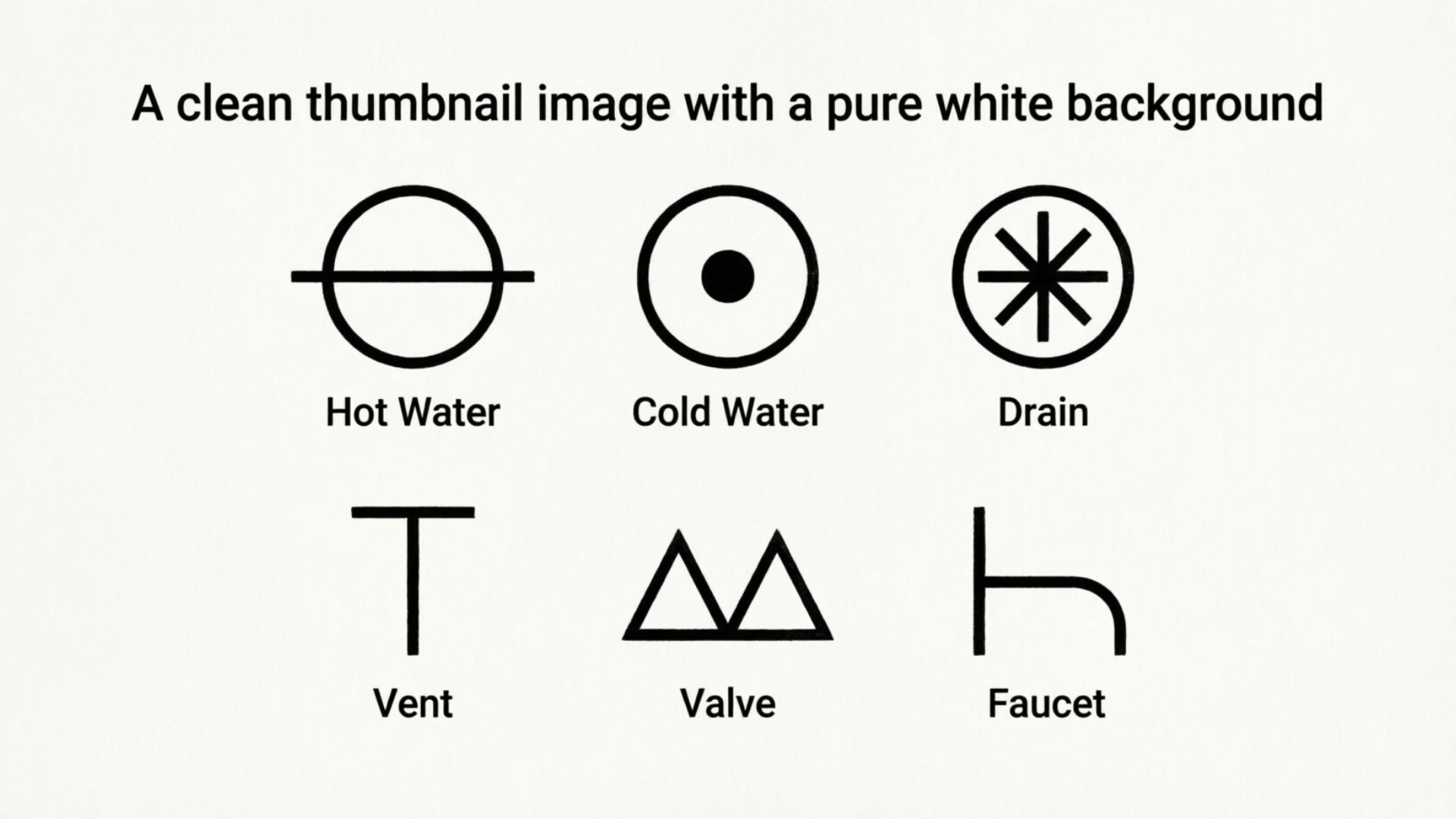
Plumbing drawings can look confusing when you first see them. Lines, letters, circles, valves, fixtures, arrows, and abbreviations can appear to form a language of their own. The good news is that you do not need to be a professional plumber to understand the basics.
Plumbing symbols are graphical marks, abbreviations, and notations used on plumbing plans, construction drawings, blueprints, riser diagrams, and isometric drawings to show fixtures, pipes, valves, drains, vents, equipment, and connections.
A toilet may be identified by a fixture symbol and the abbreviation WC. A floor drain may be labeled FD, while LAV commonly identifies a lavatory. Pipe labels such as CW, HW, and HWR can describe different water services.
However, there is an important point to remember: plumbing symbols are not completely universal. Their appearance can vary between drafting standards, jurisdictions, engineering firms, contractors, CAD libraries, and individual projects. The legend and notes on a particular drawing should always take priority.
This guide explains common plumbing symbols and their meanings, shows how symbols relate to plumbing abbreviations, and teaches you how to read them on residential and commercial plans.
What Are Plumbing Symbols? (Quick Answer)
Plumbing symbols are graphical representations and abbreviations used on construction drawings to identify plumbing fixtures, pipes, valves, drains, vents, equipment, and other components.
Common examples include:
| Common Notation | Meaning | Typical Use |
| WC | Water Closet | Toilet |
| LAV | Lavatory | Bathroom sink |
| FD | Floor Drain | Floor drainage |
| CO | Cleanout | Drain-pipe access |
| WH | Water Heater | Hot-water equipment |
| HB | Hose Bibb | Outdoor or utility hose connection |
| CW | Cold Water | Cold-water piping |
| HW | Hot Water | Hot-water piping |
| HWR | Hot Water Return | Recirculation piping |
| SAN | Sanitary | Sanitary drainage |
| V | Vent | Plumbing vent |
| VTR | Vent Through Roof | Roof-level vent termination |
The graphic appearance of each component can differ, so always compare a symbol with the project’s plumbing legend before assuming what it means.
Complete Plumbing Symbols Chart
A plumbing symbols chart is one of the fastest ways to understand a drawing. The chart below groups commonly encountered components by their purpose.
| Plumbing Component | Common Abbreviation | What It Represents |
| Water closet | WC | Toilet |
| Lavatory | LAV | Bathroom or hand-washing sink |
| Kitchen sink | KS | Kitchen sink |
| Shower | SH | Shower fixture |
| Bathtub | BT | Bathtub |
| Urinal | UR | Urinal |
| Bidet | BD | Bidet fixture |
| Floor drain | FD | Drain located at floor level |
| Floor sink | FS | Recessed floor-level plumbing receptor |
| Cleanout | CO | Access point for cleaning a drainage pipe |
| Hose bibb | HB | Hose connection |
| Water heater | WH | Equipment used to heat water |
| Water meter | WM | Measures water consumption |
| Cold water | CW | Cold-water supply |
| Hot water | HW | Hot-water supply |
| Hot-water return | HWR | Hot-water recirculation |
| Sanitary drain | SAN | Sanitary drainage |
| Waste | W | Waste piping notation |
| Vent | V | Vent piping |
| Vent through roof | VTR | Vent termination through roof |
| Roof drain | RD | Roof drainage |
| Area drain | AD | Drain serving an exterior or designated area |
| Cleanout | CO | Drainage access |
| Gate valve | — | Flow-control valve |
| Ball valve | — | Shutoff valve |
| Check valve | — | Helps prevent reverse flow |
| Pressure-reducing valve | PRV | Reduces downstream pressure |
| Backflow preventer | BFP | Helps protect the water supply from backflow |
| Sump pump | — | Pumps collected water from a sump |
| Sewage ejector | — | Pumps wastewater from a lower area |
| Grease interceptor | GI | Separates grease from wastewater |
This chart is a starting point rather than a universal symbol dictionary. The actual graphic and abbreviation used on a project should be verified against that project’s legend.
Types of Plumbing Symbols
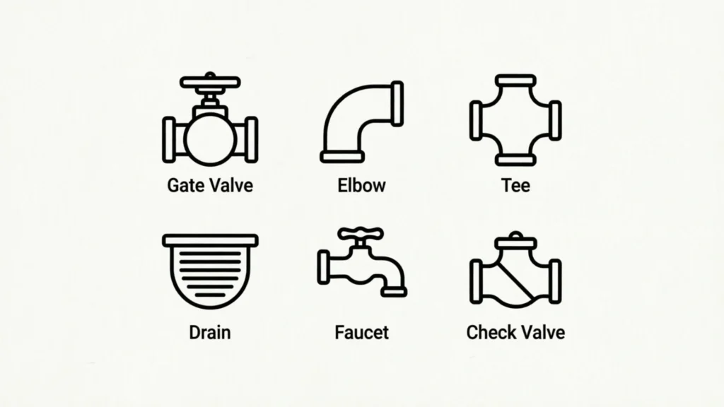
Plumbing drawings use several groups of symbols because a complete plumbing system includes much more than sinks and toilets.
Plumbing Fixture Symbols
Fixture symbols identify items that people use directly, such as toilets, sinks, showers, tubs, and urinals.
Pipe and Line Symbols
Pipe notations show the type, size, direction, or service of piping. Different line styles may distinguish new, existing, concealed, underground, or other types of piping.
Drainage Symbols
Drain symbols identify components that collect or carry wastewater and stormwater.
Vent Symbols
Vent symbols represent piping that allows drainage systems to communicate with air and helps maintain proper drainage-system operation.
Valve Symbols
Valve symbols identify devices that control, regulate, or prevent flow.
Equipment Symbols
Equipment symbols identify items such as water heaters, pumps, tanks, interceptors, and other plumbing-related equipment.
Plumbing Fixture Symbols and Meanings
Fixtures are among the easiest plumbing components to recognize once you learn their common abbreviations.
Toilet or Water Closet Symbol
A toilet is commonly identified by the abbreviation WC, meaning water closet.
On a floor plan, the graphical symbol normally resembles the shape and arrangement of a toilet viewed from above. The exact drawing varies between CAD libraries and drafting standards.
A toilet symbol may be connected to:
- A water-supply line
- A sanitary drainage line
- A venting system
- Other plumbing notes or details
Do not assume that every toilet symbol looks identical. Look for the WC label and compare the drawing with the project legend.
Lavatory Symbol
A lavatory, commonly labeled LAV, represents a bathroom or hand-washing sink.
A lavatory drawing may show:
- The basin
- Faucet location
- Hot- and cold-water connections
- Drain connection
- Trap
- Nearby wall or cabinet
The abbreviation LAV is particularly useful when a plan contains many fixtures.
Kitchen Sink Symbol
A kitchen sink may be labeled KS or another project-specific abbreviation.
On residential plans, the sink is generally shown as a rectangular or double-basin fixture within a countertop or cabinet area.
The drawing may also show connections for:
- Cold water
- Hot water
- Waste
- Dishwasher drainage
- Other appliance connections
Always check the legend because KS is not necessarily used on every drawing.
Shower Symbol
A shower is often represented by a rectangular or square enclosure containing a drain and other fixture details.
It may be labeled SH.
A detailed plan can show:
- Shower drain
- Shower valve
- Showerhead
- Water connections
- Floor or wall layout
Bathtub Symbol
A bathtub is generally drawn as a long rectangular or curved fixture with enough detail to distinguish it from a shower.
It may be labeled BT or another project-specific abbreviation.
A plumbing plan can show both the tub and its water-supply and drainage connections.
Urinal Symbol
A urinal is a plumbing fixture commonly found in commercial or institutional restrooms.
It may be abbreviated UR.
Because commercial drawings can contain several similar fixtures, the abbreviation helps distinguish a urinal from a lavatory or other fixture.
Bidet Symbol
A bidet is a bathroom fixture designed for personal hygiene.
It may be labeled BD or another abbreviation established by the drawing legend.
The symbol generally represents the fixture from a plan-view perspective.
Floor Drain Symbol
A floor drain, commonly abbreviated FD, collects water from a floor surface.
Floor drains are often found in:
- Bathrooms
- Mechanical rooms
- Utility rooms
- Commercial kitchens
- Garages
- Laundry areas
- Other locations where floor drainage is needed
The exact graphic can vary. Some drawings use a circular grate-like symbol, while others use a project-specific representation.
Floor Sink Symbol
A floor sink is a recessed floor-level plumbing receptor that can receive indirect waste from equipment or fixtures.
It may be abbreviated FS.
Floor sinks are particularly relevant in commercial kitchens and other service areas.
Hose Bibb Symbol
A hose bibb is a water outlet designed for connecting a hose.
It may be labeled HB.
Common locations include:
- Exterior walls
- Garages
- Utility areas
- Landscaping areas
- Service spaces
The symbol identifies the connection, while the project documents determine the specific piping and installation requirements.
Plumbing Pipe Symbols and Meanings
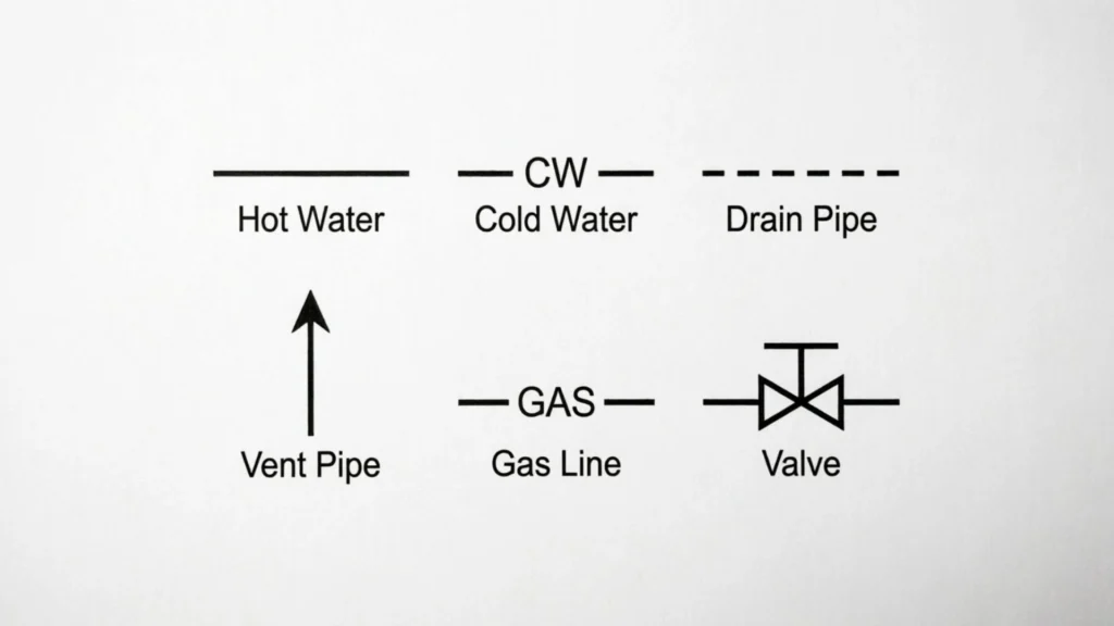
Plumbing plans use lines and labels to distinguish different piping systems.
Cold-Water Symbol
CW commonly means cold water.
A cold-water line supplies fixtures and equipment that require cold water.
For example, a bathroom plan may connect a cold-water line to:
- Toilet
- Lavatory
- Shower
- Tub
The exact line style and labeling convention depend on the drawing.
Hot-Water Symbol
HW commonly means hot water.
Hot-water piping supplies fixtures that require heated water.
A lavatory or shower may have both cold- and hot-water connections.
Hot-Water Return Symbol
HWR commonly refers to a hot-water return or recirculation line.
It is used in systems designed to circulate hot water so heated water can be available more quickly at fixtures.
Not every plumbing system has an HWR line.
Sanitary Drain Symbol
SAN is commonly used to identify sanitary drainage.
A sanitary drainage system carries wastewater from plumbing fixtures toward the building drainage system.
The drawing may show pipe sizes, slopes, cleanouts, connections, and other information alongside the sanitary piping.
Waste Piping Symbol
W can be used for waste piping, although conventions vary.
Waste piping generally carries wastewater from fixtures toward the drainage system.
The exact distinction between sanitary, waste, and other drainage terminology depends on the drawing and applicable project standards.
Vent Piping Symbol
V commonly identifies a plumbing vent.
Vent piping is part of the drainage and vent system and helps provide the necessary air pathway associated with drainage piping.
A plan may show individual vents, common vents, vent stacks, or other vent arrangements.
Vent Through Roof Symbol
VTR commonly means vent through roof.
It identifies a vent that terminates through the roof.
The actual roof penetration and installation details should be confirmed using the project drawings and specifications.
Storm Drainage Symbol
Storm drainage symbols identify piping and components that handle rainwater.
They may be associated with:
- Roof drains
- Area drains
- Site drainage
- Storm leaders
- Underground storm piping
Storm and sanitary systems should not be assumed to be the same system simply because both carry water.
Plumbing Line Types and What They Mean
The lines themselves can communicate important information.
Water Supply Lines
Water-supply lines represent piping that delivers water to fixtures and equipment.
They may be identified as:
- CW
- HW
- HWR
- Other project-specific services
Drainage Lines
Drainage lines carry wastewater away from fixtures.
A plan may identify:
- Sanitary drainage
- Waste piping
- Storm drainage
- Other specialty drainage
Vent Lines
Vent lines are part of the drainage and vent system and may connect fixtures or drainage branches with larger vent piping.
Underground Plumbing Lines
Underground piping may be represented with a particular line style or note.
The exact convention varies, so the drawing legend is especially important.
Existing and New Plumbing Lines
Renovation drawings often distinguish existing piping from new work.
A drawing may use different line styles, weights, notes, or graphic conventions for:
- Existing piping
- New piping
- Removed piping
- Abandoned piping
- Future piping
Never assume a line is new simply because it appears on a plumbing plan.
Plumbing Valve Symbols and Meanings
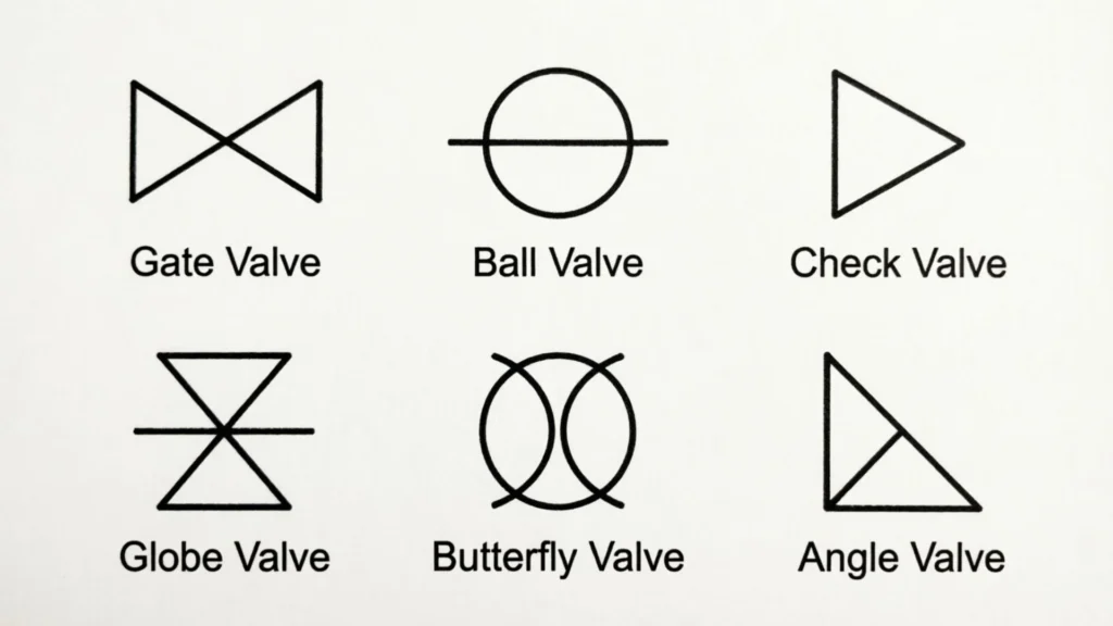
Valves are important because they control, regulate, or protect fluid systems.
Shutoff Valve
A shutoff valve allows a section of piping or equipment to be isolated.
It can be useful during:
- Maintenance
- Repairs
- Fixture replacement
- Emergency isolation
The graphical representation depends on the drafting standard.
Gate Valve
A gate valve is generally used as an isolation valve rather than for routine throttling.
A plumbing drawing may identify it with a standardized or project-specific graphic.
Ball Valve
A ball valve uses a rotating internal element to control flow.
It is commonly used where quick shutoff is useful.
Check Valve
A check valve is designed to permit flow in one direction and resist reverse flow.
The drawing may use an arrow or other graphic convention to communicate the permitted direction.
Butterfly Valve
A butterfly valve uses a rotating disc to control flow.
It is often associated with larger piping systems and may appear more frequently in commercial or mechanical applications.
Pressure-Reducing Valve
A PRV, or pressure-reducing valve, is used to reduce water pressure to a controlled downstream level.
Its symbol and installation requirements should be checked against the project’s drawings and specifications.
Pressure-Relief Valve
A pressure-relief valve provides a means of relieving pressure when conditions require it.
These valves can be especially important around pressure-producing or heating equipment.
Mixing Valve
A mixing valve combines hot and cold water to produce water at a controlled temperature.
The exact symbol and abbreviation vary by project.
Backflow Preventer
A backflow preventer helps protect a potable water supply from unwanted reverse flow.
It can appear in commercial, irrigation, mechanical, and other applications where backflow protection is required.
Plumbing Drain and Trap Symbols
Drainage components are essential parts of plumbing plans.
Floor Drain
A floor drain collects water at floor level and connects to the drainage system.
The plan may show its location with a circular or other project-specific symbol and the abbreviation FD.
Roof Drain
A roof drain collects rainwater from a roof and directs it into a storm-drainage system.
It may be labeled RD.
A roof-drain symbol may be accompanied by pipe size, leader information, overflow information, or other details.
Area Drain
An area drain collects water from a designated outdoor or indoor area.
It may appear around:
- Courtyards
- Patios
- Parking areas
- Mechanical spaces
- Exterior walkways
Trench Drain
A trench drain is a long drainage channel used to collect surface water.
It can be found in:
- Garages
- Commercial kitchens
- Washdown areas
- Industrial spaces
- Loading areas
Cleanout
A cleanout provides access to drainage piping for inspection, cleaning, or maintenance.
It is commonly abbreviated CO.
A cleanout can appear near:
- Changes in direction
- Long drainage runs
- Building drains
- Fixture branches
- Other locations requiring maintenance access
P-Trap
A P-trap is a plumbing trap designed to retain a water seal in a drainage connection.
On drawings, the trap may appear as a curved or U-shaped piping arrangement depending on the drawing type.
It is commonly associated with fixtures such as:
- Lavatories
- Sinks
- Showers
- Tubs
Trap Primer
A trap primer supplies water to a trap when necessary to help maintain its water seal.
Trap primers may be associated with floor drains and other drainage fixtures.
The exact symbol should be checked against the project legend.
Plumbing Equipment Symbols
Plumbing plans can include equipment as well as fixtures.
Water Heater Symbol
A water heater is often abbreviated WH.
A plan may identify:
- Water heater location
- Cold-water connection
- Hot-water connection
- Recirculation piping
- Drain or relief connections
- Fuel or electrical information where applicable
The plumbing drawing may be coordinated with mechanical, electrical, or equipment drawings.
Water Meter Symbol
A water meter measures water consumption.
It may be abbreviated WM.
A building plan may show the meter near the service entrance or another designated location.
Sump Pump
A sump pump removes collected water from a sump basin.
It is commonly associated with:
- Basements
- Foundations
- Below-grade spaces
- Drainage systems
Sewage Ejector
A sewage ejector pumps wastewater from areas where gravity drainage is not sufficient.
It may be found in:
- Below-grade bathrooms
- Basements
- Lower-level plumbing systems
Grease Interceptor
A grease interceptor separates fats, oils, and grease from wastewater before the wastewater enters the drainage system.
It is commonly associated with commercial food-service facilities.
Expansion Tank
An expansion tank may be included in water-heating systems to accommodate thermal expansion.
Its exact symbol and abbreviation vary by project.
Pressure Gauge
A pressure gauge provides a visual indication of pressure.
It may be shown near pumps, water systems, or other equipment where pressure monitoring is required.
Plumbing Abbreviations and Their Meanings
Plumbing abbreviations are not the same as graphical plumbing symbols, but the two are often used together.
| Abbreviation | Common Meaning |
| WC | Water Closet |
| LAV | Lavatory |
| KS | Kitchen Sink |
| SH | Shower |
| BT | Bathtub |
| UR | Urinal |
| BD | Bidet |
| FD | Floor Drain |
| FS | Floor Sink |
| CO | Cleanout |
| HB | Hose Bibb |
| WH | Water Heater |
| WM | Water Meter |
| CW | Cold Water |
| HW | Hot Water |
| HWR | Hot Water Return |
| SAN | Sanitary |
| W | Waste |
| V | Vent |
| VTR | Vent Through Roof |
| RD | Roof Drain |
| AD | Area Drain |
| PRV | Pressure-Reducing Valve |
| BFP | Backflow Preventer |
| GI | Grease Interceptor |
Why Abbreviations Can Be Confusing
The same letters may have different meanings in different industries or even different drawing sets.
For example, an abbreviation that means one thing on an architectural drawing might have another meaning on a plumbing drawing.
This is why the project’s legend and abbreviation list should always be checked first.
Plumbing Pipe Material Abbreviations
Material codes can appear alongside plumbing symbols.
| Abbreviation | Common Meaning |
| PVC | Polyvinyl Chloride |
| CPVC | Chlorinated Polyvinyl Chloride |
| PEX | Cross-Linked Polyethylene |
| ABS | Acrylonitrile Butadiene Styrene |
| CI | Cast Iron |
| CU | Copper |
| HDPE | High-Density Polyethylene |
| SS | Stainless Steel |
These abbreviations describe materials rather than fixtures or symbols.
For example:
PVC tells you something about the pipe material.
WC identifies a water closet.
Those are different types of information.
Plumbing Symbols Legend: How to Read It
A plumbing legend is one of the most important parts of a drawing set.
It acts as the project’s reference key.
A legend may explain:
- Fixture symbols
- Valve symbols
- Pipe symbols
- Abbreviations
- Line styles
- Equipment symbols
- Material codes
- General notes
Why the Legend Comes First
Suppose you see an unfamiliar circle on a drawing.
Instead of guessing what it means, find the plumbing legend and compare the graphic.
The same principle applies to abbreviations.
If a drawing uses FD, don’t automatically assume its meaning without checking the legend. In most plumbing contexts it may mean floor drain, but project-specific conventions should be followed.
What If There Is No Legend?
If the drawing does not contain a clear legend, review:
- General plumbing notes
- Drawing schedules
- Related detail drawings
- Riser diagrams
- Specifications
- Other sheets from the same project
If the meaning is still unclear, ask the responsible designer, engineer, architect, contractor, or other qualified professional rather than making a construction decision based on a guess.
How to Read Plumbing Symbols on a Blueprint
Reading a plumbing plan becomes easier when you follow a consistent process.
Step 1: Find the Plumbing Sheet
Look for the plumbing drawing number and title.
A project may contain several plumbing sheets covering different floors or systems.
Step 2: Find the Legend
Read the symbols and abbreviations before interpreting the plan.
Step 3: Identify the Fixtures
Start with recognizable fixtures such as:
- Toilets
- Sinks
- Showers
- Tubs
- Floor drains
Step 4: Identify the Water-Supply Lines
Look for labels such as:
- CW
- HW
- HWR
Then trace where those lines connect.
Step 5: Follow Drainage Piping
Look for sanitary or waste lines leaving fixtures.
Pay attention to pipe sizes, direction indicators, slopes, and elevation information when provided.
Step 6: Find Vent Piping
Look for vent notation and connections.
Vent systems may become easier to understand when viewed together with the riser diagram.
Step 7: Identify Valves
Locate shutoff, check, pressure-control, and other valves.
Step 8: Check Equipment
Find water heaters, pumps, meters, interceptors, and other equipment.
Step 9: Review Notes and Details
A symbol rarely tells the whole story.
Look for associated notes, schedules, specifications, and detail references.
Step 10: Compare With Other Drawings
A floor plan may show horizontal locations, while a riser or isometric drawing may explain vertical relationships and connections.
How to Identify an Unknown Plumbing Symbol
Finding an unfamiliar symbol is normal, especially for beginners.
Use this simple process.
Does It Represent a Fixture?
Look around bathrooms, kitchens, utility rooms, and other occupied spaces.
Possible matches include:
- WC
- LAV
- KS
- SH
- BT
- UR
- FD
Is It Located Directly on a Pipe?
It may represent:
- Valve
- Fitting
- Cleanout
- Connection
- Pipe accessory
Is It on the Floor?
Consider:
- Floor drain
- Floor sink
- Cleanout
- Trench drain
- Other drainage component
Does It Have Letters Beside It?
Compare the letters with the abbreviation list.
Is There an Arrow?
An arrow may communicate flow direction or another drawing-specific relationship.
Do not assume an arrow always means the same thing without checking the legend.
Does It Appear on a Riser?
If the symbol appears on a riser diagram, its purpose may be easier to understand when viewed in relation to vertical piping.
Plumbing Symbols for House Plans
Residential plumbing drawings generally contain a familiar group of fixtures and services.
Bathroom Plumbing Symbols
A bathroom may include:
- WC for toilet
- LAV for lavatory
- SH for shower
- BT for bathtub
- FD for floor drain where provided
Kitchen Plumbing Symbols
A kitchen plan may include:
- Kitchen sink
- Cold-water connection
- Hot-water connection
- Waste connection
- Dishwasher connection
- Other appliance-related piping
Laundry Plumbing Symbols
Laundry areas can include:
- Washing-machine water connections
- Drain connections
- Standpipe
- Floor drain where provided
Utility Room Plumbing Symbols
Utility spaces may include:
- Water heater
- Floor drain
- Water meter
- Shutoff valves
- Other equipment
The actual plumbing arrangement depends on the house design and project requirements.
Residential vs Commercial Plumbing Symbols
The same general principles apply to both residential and commercial drawings, but commercial plans usually contain more complex systems.
Residential Plumbing Plans
A residential plan often focuses on:
- Toilets
- Lavatories
- Showers
- Bathtubs
- Kitchen sinks
- Laundry connections
- Water heaters
- Hose bibbs
- Basic drainage and vent piping
Commercial Plumbing Plans
Commercial projects may contain:
- Multiple fixture groups
- Floor sinks
- Grease interceptors
- Backflow preventers
- Large water services
- Pumps
- Commercial water heaters
- Specialty drains
- Complex drainage systems
- Multiple risers
- Equipment connections
This is why a commercial plumbing drawing can appear much more complicated than a typical house plan.
Plumbing Floor Plan vs Riser vs Isometric Drawing
Different plumbing drawings communicate different types of information.
| Drawing Type | Main Purpose | What You Learn |
| Plumbing floor plan | Horizontal layout | Fixture and pipe locations |
| Riser diagram | Vertical relationships | How piping connects between levels |
| Isometric drawing | Three-dimensional piping relationships | Pipe routing and connections |
| Detail drawing | Specific installation | How a component or assembly is arranged |
| Schedule | Equipment or fixture information | Model, type, size, or specification information |
Plumbing Floor Plan
A floor plan gives you a view of the plumbing system in relation to rooms and building spaces.
It is useful for identifying where fixtures and pipes are located.
Plumbing Riser Diagram
A riser diagram focuses on vertical relationships.
It can be especially helpful in buildings with multiple floors.
Plumbing Isometric Drawing
An isometric drawing gives a three-dimensional representation of piping.
It can make complex connections easier to visualize.
Plumbing Symbols on Architectural Floor Plans
Plumbing information may appear alongside architectural information.
You may need to coordinate plumbing symbols with:
- Walls
- Doors
- Cabinets
- Structural elements
- Electrical components
- HVAC systems
- Equipment
For example, a bathroom sink may appear on an architectural floor plan while the plumbing drawing provides more detailed information about its water and drainage connections.
This coordination is important because a fixture’s physical location must work with the piping system and the building layout.
Plumbing Flow Arrows and Direction Symbols
Arrows can provide important information on plumbing drawings.
Depending on the drawing convention, an arrow may indicate:
- Direction of flow
- Direction of drainage
- Pump discharge
- Valve or equipment orientation
- Another project-specific relationship
Do not interpret an arrow by appearance alone.
Always compare it with the legend, notes, and surrounding pipe labels.
How Pipe Sizes Are Shown on Plumbing Plans
Pipe sizes are often written near or along piping.
A notation might look similar to:
1/2 in. CW
or
3/4 in. HW
These examples communicate pipe size together with the service being carried.
However, exact notation varies between projects.
When reading pipe sizes, check:
- Unit system
- Pipe service
- Pipe tag
- Material
- Drawing notes
- Specifications
- Schedule information
A pipe-size label should not be interpreted independently of the drawing.
Existing, New, and Demolition Plumbing
Renovation plans often need to show what already exists and what will change.
A project may distinguish:
- Existing piping
- New piping
- Piping to be removed
- Abandoned piping
- Future piping
Different line types, weights, colors, symbols, or notes may be used.
Because these conventions vary, the project’s demolition and plumbing legends are essential.
Plumbing Symbols in CAD and BIM Drawings
Modern construction documents are often created with CAD or BIM software.
Digital drafting makes it possible to use libraries containing:
- Plumbing fixtures
- Valves
- Pipe fittings
- Equipment
- Drainage components
- Annotations
- Tags
However, using CAD or BIM software does not make plumbing symbols universally identical.
A company may customize its digital library to match its preferred drafting standards.
That means a symbol generated by one software library can look different from a similar component in another project.
Common Plumbing Blueprint Reading Mistakes
Even experienced readers can misunderstand a drawing if they overlook important information.
Mistake 1: Assuming Every Symbol Is Universal
There is no single appearance that should be assumed for every plumbing symbol.
Better approach: Check the project legend.
Mistake 2: Confusing Symbols With Abbreviations
WC is an abbreviation, while the graphical toilet representation is a symbol.
Better approach: Learn both together.
Mistake 3: Looking Only at Fixtures
Fixtures are only one part of a plumbing system.
Better approach: Study water supply, drainage, vents, valves, and equipment too.
Mistake 4: Ignoring Pipe Labels
A line without context can be difficult to interpret.
Better approach: Read the service label, size, notes, and related details.
Mistake 5: Ignoring the Riser Diagram
A floor plan may not fully explain vertical piping.
Better approach: Compare floor plans with risers and isometrics.
Mistake 6: Treating an Abbreviation as Universal
Abbreviations can vary by project.
Better approach: Use the drawing’s abbreviation list.
Mistake 7: Ignoring Drawing Notes
Important information may be explained in notes instead of directly beside a symbol.
Better approach: Review notes, schedules, details, and specifications.
Plumbing Symbols vs Electrical Symbols
Plumbing and electrical drawings can both contain lines, circles, abbreviations, and equipment symbols, but they represent different systems.
Plumbing Drawings
Plumbing drawings commonly identify:
- Fixtures
- Water pipes
- Drainage
- Vents
- Valves
- Plumbing equipment
Electrical Drawings
Electrical drawings commonly identify:
- Outlets
- Switches
- Lighting
- Panels
- Circuits
- Electrical equipment
If several disciplines are included in one drawing set, always confirm the sheet discipline and legend before interpreting a symbol.
Plumbing Symbols vs HVAC Symbols
HVAC drawings focus primarily on heating, ventilation, and air-conditioning systems.
They may contain:
- Ductwork
- Air terminals
- Diffusers
- Fans
- Mechanical equipment
- Heating and cooling systems
Plumbing drawings instead focus on water, drainage, vents, fixtures, and related equipment.
Because the drawings may be coordinated, the same room can appear on several discipline sheets with completely different symbols.
Are Plumbing Symbols Universal?
No. Common plumbing symbols and abbreviations are widely recognized, but their exact graphical appearance and notation are not universally identical.
Differences can result from:
- Drafting standards
- Building codes
- Local practices
- Engineering firms
- Architectural firms
- CAD libraries
- BIM families
- Contractor conventions
- Project-specific legends
The safest rule is simple:
When the project legend conflicts with a general plumbing-symbol guide, follow the project legend.
Why Plumbing Symbols Matter in Construction
Plumbing symbols help different people understand the same building system.
They can support communication between:
- Architects
- Plumbing designers
- Engineers
- Contractors
- Plumbers
- Inspectors
- Project managers
- Building owners
A clear drawing can communicate fixture locations, pipe routing, drainage systems, equipment, valves, and connections without requiring long written descriptions beside every component.
For that reason, learning plumbing symbols is useful not only for students but also for anyone who needs to understand construction documents.
How Beginners Can Learn Plumbing Symbols
You do not need to memorize every symbol at once.
Start with the most common groups.
Learn Fixtures First
Memorize:
- WC
- LAV
- KS
- SH
- BT
- FD
Learn Water Services Next
Understand:
- CW
- HW
- HWR
Learn Drainage and Vents
Then study:
- SAN
- W
- V
- VTR
- CO
- FD
Learn Valves
Move on to:
- Shutoff valves
- Gate valves
- Ball valves
- Check valves
- Pressure-control valves
- Backflow-prevention devices
Practice With a Complete Drawing
Once you know the basic symbols, choose a simple plumbing plan and identify every fixture, pipe label, drain, vent, valve, and equipment symbol.
This is much more effective than memorizing a long list without seeing how the components work together.
A Simple Plumbing Plan Walkthrough
Imagine a small bathroom containing a toilet, lavatory, and shower.
You might identify:
WC → toilet
LAV → lavatory
SH → shower
The fixtures may connect to:
CW → cold-water supply
HW → hot-water supply
The drainage system may be identified with:
SAN → sanitary drainage
A floor drain, if provided, may be labeled:
FD → floor drain
A nearby drainage access point may be:
CO → cleanout
A vent may be identified as:
V → vent
The important lesson is that you should not study each symbol independently. Look at how the fixture, water supply, drainage, vent, and access components relate to one another.
Plumbing Symbols Reference Checklist
When reading a plumbing drawing, use this quick checklist:
- Find the plumbing legend.
- Identify the drawing scale.
- Review abbreviations.
- Identify plumbing fixtures.
- Locate water-supply piping.
- Locate drainage piping.
- Identify vent piping.
- Find valves.
- Find cleanouts.
- Identify plumbing equipment.
- Check pipe sizes.
- Look for flow arrows.
- Review notes.
- Check schedules.
- Review details.
- Compare related floor plans.
- Check riser diagrams.
- Check isometric drawings when provided.
- Never assume an unfamiliar symbol without verification.
Frequently Asked Questions
What are plumbing symbols?
Plumbing symbols are graphical representations and abbreviations used on plumbing drawings to identify fixtures, pipes, valves, drains, vents, equipment, and other components.
What does WC mean on a plumbing plan?
WC commonly means water closet, which is another term for a toilet.
What does LAV mean in plumbing?
LAV commonly means lavatory, usually referring to a bathroom or hand-washing sink.
What does FD mean on a plumbing drawing?
FD commonly means floor drain. It identifies a drainage fixture located at floor level.
What does CO mean on a plumbing plan?
CO commonly means cleanout. A cleanout provides access to drainage piping for cleaning or maintenance.
What does CW mean in plumbing?
CW commonly means cold water and identifies a cold-water supply line.
What does HW mean in plumbing?
HW commonly means hot water and identifies a hot-water supply line.
What does HWR mean on a plumbing drawing?
HWR commonly means hot-water return. It is generally associated with a hot-water recirculation system.
What does VTR mean in plumbing?
VTR commonly means vent through roof, referring to a plumbing vent that terminates through the roof.
What is a plumbing legend?
A plumbing legend is a reference key that explains the symbols, abbreviations, line types, equipment identifiers, and other conventions used on a particular plumbing drawing.
Are plumbing symbols standardized?
Many commonly used plumbing symbols and abbreviations are recognizable across the industry, but their exact appearance and terminology can vary. The project-specific legend should always be treated as the primary reference.
What are the most common plumbing symbols?
Common examples include symbols for toilets, lavatories, sinks, showers, bathtubs, floor drains, cleanouts, valves, water heaters, pumps, and different water, drainage, and vent systems.
What is the difference between a plumbing symbol and a plumbing abbreviation?
A symbol is generally a graphical representation of a component, while an abbreviation uses letters or numbers to identify a component, system, or other drawing information.
For example, a toilet may have a graphical fixture symbol accompanied by WC.
How do you read plumbing symbols on a blueprint?
Start with the drawing legend, then identify fixtures, water-supply lines, drainage, vents, valves, equipment, pipe sizes, and notes. Compare the floor plan with riser diagrams and details when necessary.
What plumbing symbols are used in house plans?
Residential plans commonly show toilets, lavatories, showers, bathtubs, kitchen sinks, floor drains, water heaters, hose bibbs, cleanouts, water-supply lines, drainage, and vents.
What is the difference between a plumbing floor plan and a riser diagram?
A plumbing floor plan primarily shows the horizontal location of fixtures and piping, while a riser diagram focuses on vertical relationships and connections between floors or levels.
Why do plumbing symbols look different on different drawings?
Different drafting standards, CAD libraries, engineering firms, project conventions, and jurisdictions can influence symbol appearance. The drawing legend explains the conventions used for that specific project.
Can I identify every plumbing component from its symbol alone?
Not always. Symbols provide important information, but you may also need abbreviations, notes, pipe sizes, schedules, details, specifications, and related drawings to understand a component correctly.
Conclusion
Understanding plumbing symbols makes construction drawings much easier to read. Once you recognize common fixture symbols, pipe labels, drainage notations, vents, valves, equipment, and abbreviations, a plumbing plan becomes far less intimidating.
The most important habit is to check the project legend before interpreting an unfamiliar symbol. Common conventions are helpful, but plumbing symbols and abbreviations can vary between drawings and projects.
If you are a beginner, start with the basics: learn WC, LAV, FD, CO, CW, HW, HWR, SAN, V, and VTR. Then move into valves, equipment, drainage components, pipe sizes, and complete blueprint interpretation.
For homeowners, students, designers, and construction professionals, the goal is not simply to memorize symbols. The real skill is learning how fixtures, water supply, drainage, vents, valves, and equipment work together as one plumbing system.

Adam Sullivan is a dedicated writer who enjoys transforming everyday topics into engaging and informative content. His writing focuses on making complex ideas simple, practical and enjoyable for readers of all backgrounds. Adam is also the fictional author of The Lantern Beyond Autumn Hills and Where the Morning Horizon Waits. Outside of writing, he enjoys photography, traveling and discovering inspiration through new experiences. He believes great content should be both helpful and easy to connect with.
 Dylan Anderson